


Featured Products
Easy Guide to Installing a Small GPS Tracker in Your Heavy Equipment
Written by Luis Montes Updated On May 14, 2024
A heavy equipment GPS tracking device is a cost-effective way to protect your equipment against theft.
Modern equipment has integrated devices for benefits besides localization and theft protection, like telematics, automation, maintenance, and predictive analytics. You can read more about it in our article “How Does Quality Mining Equipment Pave the Path to Success?”
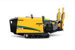
On used equipment, a GPS installation is a straightforward task. We’ll explain how to install a GPS immobilizer on a John Deere 26G mini excavator. The process is pretty much the same on other makes and models.
Remember, while we want to keep the device as hidden as possible, try not to enclose it with metal since it will disrupt satellite reception.
If you´d like to watch this GPS tracker installation guide rather than read about it, here’s the link to our YouTube video:
Tools You’ll Need
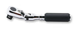
- Ratchet and sockets set.
- Crimper.
- Plastic wire puller (plastic fish).
- Multimeter.
- Utility knife.
- Pointy tool.
- Five pins 12-volt relay (depending on your machine, it could be 12 or 24 volts).
- Cutters.
- Power drill.
- Soldering pencil.
- Ring and insulated terminals.
- Heat shrinks.
- Heat gun.
- Split loom.
- 1-ft 14-AWG wire (for the immobilizer connection).

Choose an Install Location

We chose a spot behind the excavator’s left-hand panel. The GPS tracker will be out of sight but not completely enclosed.
We’ll power the excavator GPS from the fuse block and enclose the wiring with a black loom or tape. The fuse box is underneath the seat of the 26G. Other power options are the ignition and the battery. Whatever works best for you, as long as you keep the installation hidden.
Set the GPS Harness

First, cover the GPS harness with the split loom.
Remove the three 17 mm bolts holding the left-hand side panel of the excavator.
Remove the floor mat, and open the pattern changer panel (see the image below).

There’s an access hole at the bottom of the pattern changer compartment. Pass a plastic wire puller through the hole to where we’ll install the GPS tracker (if you can’t pass the plastic puller, try doing it the other way).
Now, tape the harness to the plastic and pull it through — spray silicone will make it easier.
To access the fuse box for this particular model, you must route the wires through two grommets (see the GIF below).

Leave enough length to the harness at each end for the connections. We left about 1 foot at each end.
Identify the Connection Wires

Remove 2 Phillips screws holding the fuse box. Pull the harness a bit to make yourself room to work. Cut the loom to expose the wires from the fuse box.
Ground the multimeter, and with the ignition key turned off, find the ignition, the starter, and a constant 12-volt wire.
The readings you must look out for in the multimeter are the following:
- For the 12-volt wire, the multimeter must show a constant value above 12 volts.
- The multimeter must show zero voltage for the ignition wire (red and white for the 26G). When turning the key on, the multimeter must show a bit less than 12 volts because several electrical circuits are on. When cranking the starter, the voltage should drop. When releasing it, the multimeter should be above 12 volts.
- The multimeter must show zero voltage for the starter wire while the key is off. You should also see zero voltage with the key on, or it’ll move above zero. Crank the engine, and you should first see the meter jump (35 volts or so) and then go back off. For this particular model, the starter wire is blue and white.
Cut the starter wire further back from the fuse box (about 4 to 6 inches), so you have space to connect the immobilizer relay. Double-check that you cut the correct wire by cranking the engine (The machine shouldn’t start).
Connect the GPS Wire Harness To the Relay

Start by grounding the black wire. We ground off to a metal bracket high above the fuse box (that’s up to you).
Use the crimper to attach a ring terminal to the ground wire and put a dab of solder to secure it. Finish with a heat shrink to cover most of the metal. The heat shrink will keep moisture out and make everything look neat.
Next, cut the power (red) and output (yellow) wires from the GPS device to a suitable length for the connection (approx. 6 inches from the loom’s end). Double the ignition wire’s length since it’ll also go to the relay.
For all wire ends, strip off 1.5 inches from the insulation.
Put red insulated crimp terminals on the ignition and output wires.
Connect the ignition wire to pin 86 on the relay and the negative output wire to pin 85. Pins 86 and 85 are the ones that activate the magnetic coil in the relay, triggering the switch.
Be aware of some installation instructions showing a constant power wire connected to pin 86. It’s a bad idea since the relay will stay on regardless of the key. It’ll kill your battery fairly quickly. That’s why we recommend using the ignition.
Strip off 1.5 inches from the insulation at each end of the previously cut starter wire and put blue insulated crimp terminals. The reason for blue terminals is that they accept a thicker gauge. Remember, our relay starter wire is 14 gauge versus the original 18 gauge on the excavator.
Connect one end of the 14 gauge wire to pin 30 on the relay and the other to pin 87a.

So, what is going on here?
We are making a negative trigger relay connection. The GPS device will act as a switch to trigger the relay and cut the starter circuit.
When the relay is at rest, pins 30 and 87a are connected, allowing the machine to crank. In the event of theft, the owner sends a signal to the GPS, closing the circuit to activate the magnetic coil in the immobilizer relay, connecting pin 30 to pin 87. Since there’s nothing on pin 87, no current will flow through the starter circuit, and the machine won’t crank.
Since pin 87 will be exposed, consider connecting a red insulated crimp terminal.
For further details, see the diagram below.

Connect the GPS Wire Harness to the Fuse Box

Which wire should you use to power the device? Since the GPS device draws little current (about 1/2 amp), we chose a wire protected by a 5-amp fuse.
For this connection, we used the poke-and-wrap technique. Here’s what you must do if you want to use it:
- Remove about 1.5 inches from the insulation of the wire on the excavator.
- Take a sharp or pointy tool and poke through the exposed wire, creating a loop.
- Twist the end of the power wire from the GPS and poke it through the loop you created.
- Squeeze the loop and twist the bare wire around the loop.
- Put a dab of solder on it for extra protection.
- Protect the connection with heat shrinks.
Repeat the process with the ignition wire.
You can connect the starter wires in any configuration. Strip off the ends, cross them, twist, put some solder, and finish with a heat shrink.
Because we messed around with the fuse block wires, we wrapped them up with a zip tie and some tape.
Finish by putting back the fuse box with its screws and hiding the immobilizer relay.
Test the GPS Tracker

First, crank the engine to test the connection you just made.
Next, plug in your GPS.
You must do two initial tests:
- Make sure the device LED lights up.
- Activate the device and look it up online to see if it’s reporting.
We need the IMEI number (10+ digits) to activate this GPS device. Depending on the weather, the activation process can take 30 minutes to a few hours. Turning on the ignition speeds up the registration process.
Once you have confirmation that the device is online and reporting, do three final tests:
- GPS location.
- Ignition reporting by turning the key on and off.
- The immobilizer.
Turn the immobilizer on via the GPS app, and try cranking the machine. Remember, the GPS acts as a switch to open and close the circuit, triggering the relay. The excavator shouldn’t crank.
Finally, turn off the immobilizer and try cranking the machine again.
Troubleshooting the Device
Not getting a signal?
First, try to go outside for better cellular reception.
Also, check the power grounds and your connections.
You can do two more tests:
- Use the multimeter to check the voltages of the ground and power wires at the GPS harness — 0 and 12 volts, respectively.
- Unplug the device. Connect the GPS ground (black) and output (yellow) wires and try cranking the machine. It shouldn’t start.
Conceal the GPS Tracker

Cover the exposed wiring with a loom and some tape at the GPS end.
Conceal the GPS tracker until it’s not visible from the louvered part of the machine’s cover. Make sure to stay away from moving parts.