


Easy Guide to Installing a Small GPS Tracker in Your Heavy Equipment
Written by
Updated On May 14, 2024
Featured Tools
+

3-5 Day FREE Shipping over $150 Call 855-702-2932 to order on the phone

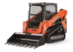
Shop Quality Heavy Equipment Rubber Tracks
Premium rubber tracks to boost performance on any type of terrain
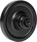
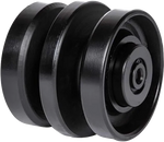
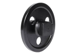
Shop AllShop Quality Heavy Equipment Undercarriage Parts
Top tier heavy equipment undercarriage parts to keep your machine in peak condition
Shop AllShop Quality Heavy Equipment Tools
Get the best quality heavy equipment Tools without the worry
Shop All

Written by
Updated On May 14, 2024
+
If you´d like to watch this GPS tracker installation guide rather than read about it, here’s the link to our YouTube video:
Choose an Install Location

Set the GPS Harness


Identify the Connection Wires

Connect the GPS Wire Harness To the Relay


